Service hotline
+86 0755-83044319

release time:2025-05-08Author source:SlkorBrowse:10983
In this article, we compares current sense amplifiers and differential amplifiers, analyzing their architectures, performance characteristics, and application differences. The advantages of current sense amplifiers in bandwidth, common-mode rejection ratio (CMRR), and high-frequency applications are highlighted.
Architectural Differences Between Current Sense Amplifiers and Differential Amplifiers
Unlike differential amplifiers, which rely on input resistor networks to attenuate input voltages, current sense amplifiers typically employ a unique architecture. They utilize high-voltage input transistors to directly handle large and rapidly varying common-mode voltages while accurately amplifying small differential shunt voltages (Figure 1).
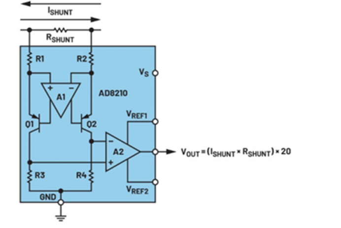
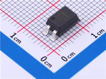
Figure 1. Example of a Current Sense Amplifier
In differential amplifiers, the input differential signal is first attenuated by a resistor network, then amplified back to the original input level with additional gain to achieve the final signal amplification at the output. Restoring the attenuated input to its original signal amplitude consumes part of the internal amplifier’s gain-bandwidth product, sacrificing bandwidth to achieve extra gain.
In contrast, current sense amplifiers do not attenuate signals due to their high-voltage input transistors, eliminating the need for additional gain to restore signal amplitude. This allows the internal op-amp to retain more bandwidth for signal amplification.
Performance Advantages of Current Sense Amplifiers
Bandwidth Advantage: For example, the AD8206 differential amplifier has a small-signal -3dB bandwidth of 100 kHz, while the AD8210 current sense amplifier offers a bandwidth of 450 kHz. The increased bandwidth of current sense amplifiers makes them ideal for high-frequency applications or scenarios requiring detection of fast current transients.
High Common-Mode Rejection Ratio (CMRR): Current sense amplifiers generally exhibit higher CMRR, typically in the range of 100 dB to 120 dB or higher, whereas most differential amplifiers have a CMRR between 80 dB and 100 dB.
Common-Mode Voltage Range: A trade-off for the larger bandwidth of current sense amplifiers is the absence of internal attenuation networks. This limits their ability to accept extremely high common-mode input voltages compared to differential amplifiers. However, current sense amplifiers still support high common-mode voltage ranges, typically between 80 V and 100 V.
Advantages of Current Sense Amplifiers in Fast-Changing Current Measurements
Current sense amplifiers are commonly used to measure large switching currents. When measuring these currents on the high side of a load, the common-mode voltage across the shunt resistor may rapidly fluctuate between ground level and the supply voltage.
These rapid changes can induce significant transients at the amplifier’s input. In some cases, common-mode voltage transients may exceed the signal amplitude itself. Ideally, the amplifier should only produce an output reflecting the amplified differential sense voltage. However, in practical applications, the output may exhibit a common-mode step response.
Current sense amplifiers excel at suppressing common-mode transient spikes caused by fast-changing common-mode voltage steps, making them particularly suitable for current sensing applications with rapidly varying amplitudes.
Application of Current Sense Amplifiers in Three-Phase Motor Control Systems
A prime example of rapid common-mode voltage switching occurs in the phase current measurement of a three-phase motor control system. In such systems, the controller sends pulse-width modulation (PWM) signals to the inverter stage to drive each phase of the motor (Figure 2).
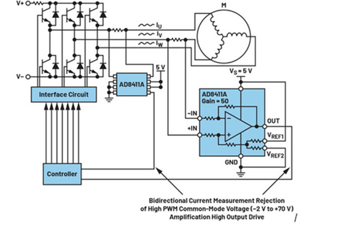
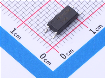
Figure 2. Three-Phase Motor Control Current Sensing
A shunt resistor is placed in series with the motor to measure the differential voltage across it, providing instantaneous current feedback. This feedback enables the controller to determine the phase of each signal. As each PWM pulse arrives, the common-mode voltage at the shunt resistor rapidly switches across the full supply range, from V- to V+. These fast PWM transitions demand amplifiers with high bandwidth and effective suppression of transient overshoots during rising and falling edges.

Site Map | 萨科微 | 金航标 | Slkor | Kinghelm
RU | FR | DE | IT | ES | PT | JA | KO | AR | TR | TH | MS | VI | MG | FA | ZH-TW | HR | BG | SD| GD | SN | SM | PS | LB | KY | KU | HAW | CO | AM | UZ | TG | SU | ST | ML | KK | NY | ZU | YO | TE | TA | SO| PA| NE | MN | MI | LA | LO | KM | KN
| JW | IG | HMN | HA | EO | CEB | BS | BN | UR | HT | KA | EU | AZ | HY | YI |MK | IS | BE | CY | GA | SW | SV | AF | FA | TR | TH | MT | HU | GL | ET | NL | DA | CS | FI | EL | HI | NO | PL | RO | CA | TL | IW | LV | ID | LT | SR | SQ | SL | UK
Copyright ©2015-2025 Shenzhen Slkor Micro Semicon Co., Ltd
