Service hotline
+86 0755-83044319
release time:2022-04-20Author source:SlkorBrowse:9354
As we know, there may be some problems in the data exchange among the sub-modules of the circuit system, which may lead to the abnormal and high-quality "circulation" of signals. For example, sometimes the working sequence of the sub-modules of the circuit is different (such as CPU and peripherals) or their signal types are different (such as sensors detecting optical signals). At this time, we should consider to deal with this problem well through corresponding interface methods.
The following key points of seven commonly used interface types in circuit design are explained:
This interface type is basically a cliche, right? Since studying analog circuit and digital circuit in college, TTL level interface can't be separated from the general circuit design. Its speed is generally limited to 30MHz, which is because there are several pF input capacitors at the input of BJT (forming an LPF). If the input signal exceeds a certain frequency, the signal will be "lost". Its driving capacity is generally up to tens of milliamps. Generally, the normal signal voltage is high. If it is close to the ECL circuit with low signal voltage, it will cause obvious crosstalk problem.
We are no stranger to it, and we often deal with it. Some semiconductor features about CMOS need not be worded here. As many people know, under normal circumstances, the power consumption and anti-interference ability of CMOS are far superior to TTL. But! Little known is that at high switching frequency, CMOS series actually consumes more power than TTL. As for why this is the case, please ask the semiconductor physics theory.
As the working voltage of CMOS can be very small at present, some FPGA cores even work at a voltage close to 1.5V, which makes the noise tolerance between levels much smaller than TTL, thus aggravating the signal judgment error caused by voltage fluctuation. As we all know, the input impedance of CMOS circuit is very high. Therefore, its coupling capacitance can be very small, without using a large electrolytic capacitor.
Because CMOS circuits usually have weak driving ability, TTL conversion must be performed before ECL circuits are driven. In addition, when designing CMOS interface circuit, we should pay attention to avoid the capacitive load being too heavy, otherwise it will slow down the rise time and increase the power consumption of the driving device (because capacitive load does not consume power).
This is an old friend of the computer system! Because its speed "runs" fast enough, it can even run to hundreds of MHz! This is because the BJT inside ECL is not saturated when it is turned on, so that the turn-on and turn-off time of BJT can be reduced, and the working speed can naturally be raised.
But, this is to pay the price! Its fatal injury: high power consumption! The EMI caused by it is worth considering, and the anti-interference ability is not much better. If anyone can compromise these two factors, then he (she) should make a fortune. It should also be noted that the general ECL integrated circuit needs negative power supply, that is to say, its output voltage is negative, so a special level shifting circuit is needed.
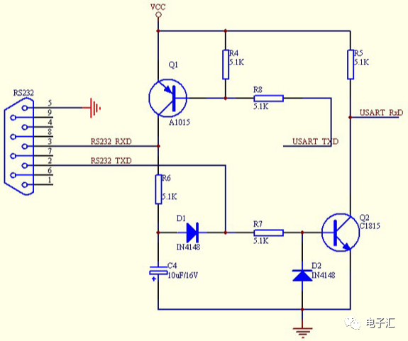
There is no one who doesn't know the basics of electronic technology (unless he or she is just a "layman" in electronic technology). It is a low-speed serial communication interface standard. It should be noted that its level standard is a bit "abnormal": the high level is -12V, while the low level is +12V. So, when we try to communicate with peripherals through computers, a level shifting chip MAX232 is naturally indispensable. But we have to be aware of its shortcomings, such as slow data transmission speed and short transmission distance.

It uses the relative output voltage (uA-uB) of a pair of terminals A and B to represent the signal. Generally, this differential signal will pass through a complex noise environment during signal transmission, resulting in basically the same amount of noise on both lines, and the energy of the noise will be cancelled at the receiving end, so it can realize long-distance and high-speed transmission. RS-485 interface, which is commonly used in industry, adopts differential transmission mode, and it has good anti-common mode interference ability.
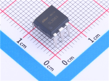
Optoelectronic coupling uses optical signal as the medium to realize the coupling and transmission of electrical signals. Its "advantage" is that it can realize electrical isolation, so it has excellent anti-interference ability. Under the condition of high operating frequency, only high-speed photoelectric isolation interface circuit can meet the needs of data transmission.
Sometimes, in order to realize the control of high voltage and high current, we must design and use the optical isolation interface circuit to connect these TTL or CMOS circuits with low level and low current as mentioned above, because the input loop and output loop of the optical isolation interface can bear a high voltage of several thousand volts, which is enough for general applications.
In addition, the input part and the output part of the optical isolation interface must adopt independent power supply respectively, otherwise, there will still be electrical connection, which is not called isolation.
Its electrical isolation characteristics are good, but the allowed signal bandwidth is limited. For example, transformer coupling, its power transmission efficiency is very high, and its output power is basically close to its input power. Therefore, for a step-up transformer, it can have a higher output voltage, but it can only give a lower current.
In addition, the high-frequency and low-frequency characteristics of the transformer are not optimistic, but its biggest feature is that it can realize impedance transformation. When matched properly, the load can obtain enough power. Therefore, the coupling interface of the transformer is very popular in the design of power amplifier circuit.


Site Map | 萨科微 | 金航标 | Slkor | Kinghelm
RU | FR | DE | IT | ES | PT | JA | KO | AR | TR | TH | MS | VI | MG | FA | ZH-TW | HR | BG | SD| GD | SN | SM | PS | LB | KY | KU | HAW | CO | AM | UZ | TG | SU | ST | ML | KK | NY | ZU | YO | TE | TA | SO| PA| NE | MN | MI | LA | LO | KM | KN
| JW | IG | HMN | HA | EO | CEB | BS | BN | UR | HT | KA | EU | AZ | HY | YI |MK | IS | BE | CY | GA | SW | SV | AF | FA | TR | TH | MT | HU | GL | ET | NL | DA | CS | FI | EL | HI | NO | PL | RO | CA | TL | IW | LV | ID | LT | SR | SQ | SL | UK
Copyright ©2015-2025 Shenzhen Slkor Micro Semicon Co., Ltd