Service hotline
+86 0755-83044319

release time:2022-03-17Author source:SlkorBrowse:8065
Operational amplifier and comparator are similar in appearance and schematic symbols, so it is difficult to distinguish them if the logo is polished. In addition, many beginners often confuse operational amplifiers with comparators, because in some applications, operational amplifiers are used as comparators in many circuits. This article shares these differences.
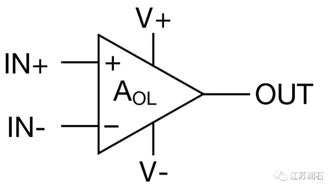
Figure 1 Schematic diagram of operational amplifier pins
The functions of the operational amplifier and comparator are described as follows
Operational amplifier is an analog chip for signal conditioning. For example, amplify, filter and sum the signals.
Comparator is a circuit that compares an analog voltage signal with a reference voltage.
Operational amplifiers are used in negative feedback systems, while comparators are generally used in open loop systems. Positive feedback can also be introduced to design hysteresis comparators.
a) The reaction speed of the operational amplifier is related to the slew rate. When a step signal is input, the operational amplifier is established at a certain speed, while the comparator immediately flips.
b) Some high-voltage operational amplifiers and Bipolar (triode) process operational amplifiers will have bidirectional clamping diodes between the two input pins (see Figure 2). The comparator has no diode with bidirectional clamping, and the influence of the input differential mode signal on the comparator is small. Therefore, when the operational amplifier is used as a comparator, it is necessary to judge whether a current limiting resistor is needed to avoid burning the operational amplifier.
C) The operational amplifier generally measures its flipping speed by bandwidth and slew rate, while the comparator uses T PHL, T PLH, T fall, trese to express the speed. A simple way to calculate the comparator speed is:
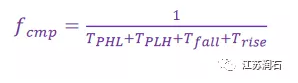
d) The output of the comparator can characterize the potential of the two input terminals. At present, the output of most comparators on the market can be compatible with TTL and CMOS levels, and the output of the comparator is always one of the positive and negative power rails. However, the output of operational amplifier is analog signal. At present, low-voltage CMOS operational amplifier can generally achieve rail-to-rail output.
E) After the output of the operational amplifier is overloaded, it takes a long recovery time; And the overload recovery time of the comparator is very short.
F) The input common-mode voltage range of some operational amplifiers does not include the positive power rail; Many comparator inputs are supported to the positive power rail.
G) The operational amplifier can be used as a comparator (in some low-speed flip situations), but the comparator cannot be used as an operational amplifier.
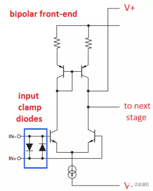
Figure 2 Operational amplifier internal input protection circuit
To sum up, the difference between the operational amplifier and the comparator is that the operational area is different, and the operational amplifier generally works in the linear area (closed loop). The input voltage and output voltage of the linear regional operational amplifier have a certain proportional relationship, which can be used for amplification.
The comparator works in the nonlinear region (open loop), that is, in this region, the input and output of the comparator are no longer proportional to each other, so there is no amplification. At this stage, its output has only two states, namely "high level" and "low level", which are the concepts of "1" and "0" if represented by numbers. Generally, there are two regions of linearity and nonlinearity in general-purpose amplifiers, but there is only one region of nonlinearity in the comparator. To sum up simply, the amplifier can be used as a comparator (pay attention to the common-mode input voltage range) when the speed requirement is not high, but the comparator cannot be used as an amplifier.
Their internal circuit structures are different, and the output stage of operational amplifier is generally push-pull circuit structure. However, the output stage of some comparators is open drain or open source architecture, which requires the pull-up resistor or pull-down resistor to match the voltage of the subsequent digital circuit.
Comparison of structure of additional open-drain output and push-pull output;
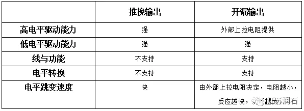
Table 1 Comparison between open-drain output and push-pull output
Disclaimer: This article is reproduced from "Jiangsu Runshi". This article only represents the author's personal views, and does not represent the views of Sacco Micro and the industry. It is only for reprinting and sharing to support the protection of intellectual property rights. Please indicate the original source and author when reprinting. If there is any infringement, please contact us to delete it.
Company Tel: +86-0755-83044319
Fax/fax:+86-0755-83975897
Email: 1615456225@qq.com
QQ: 332496225 Manager Qiu
Address: Room 809, Block C, Zhantao Technology Building, No.1079 Minzhi Avenue, Longhua New District, Shenzhen

Site Map | 萨科微 | 金航标 | Slkor | Kinghelm
RU | FR | DE | IT | ES | PT | JA | KO | AR | TR | TH | MS | VI | MG | FA | ZH-TW | HR | BG | SD| GD | SN | SM | PS | LB | KY | KU | HAW | CO | AM | UZ | TG | SU | ST | ML | KK | NY | ZU | YO | TE | TA | SO| PA| NE | MN | MI | LA | LO | KM | KN
| JW | IG | HMN | HA | EO | CEB | BS | BN | UR | HT | KA | EU | AZ | HY | YI |MK | IS | BE | CY | GA | SW | SV | AF | FA | TR | TH | MT | HU | GL | ET | NL | DA | CS | FI | EL | HI | NO | PL | RO | CA | TL | IW | LV | ID | LT | SR | SQ | SL | UK
Copyright ©2015-2025 Shenzhen Slkor Micro Semicon Co., Ltd
