Service hotline
+86 0755-83044319

release time:2025-07-21Author source:SlkorBrowse:1267
1. What is the Hall Effect?
The Hall effect is caused by the interaction between the corresponding electric and magnetic fields of charged particles (such as electrons). For a more vivid and intuitive understanding, you can refer to the animation diagram of the Hall effect principle below.
2. Principle of the Hall Effect
When a conductive plate is connected to a circuit with a battery, current starts to flow. Charge carriers will move along a linear path from one end of the plate to the other. The movement of charge carriers generates a magnetic field. When a magnet is placed close to the plate, the magnetic field of the charge carriers becomes distorted, which disrupts the straight-line flow of the charge carriers. The force that disturbs the direction of the charge carriers' flow is called the Lorentz force.
Due to the distortion of the charge carriers' magnetic field, negatively charged electrons will deflect to one side of the plate, while positively charged holes will deflect to the other side. A potential difference, known as the Hall voltage, will be generated between the two sides of the plate, which can be measured with an instrument.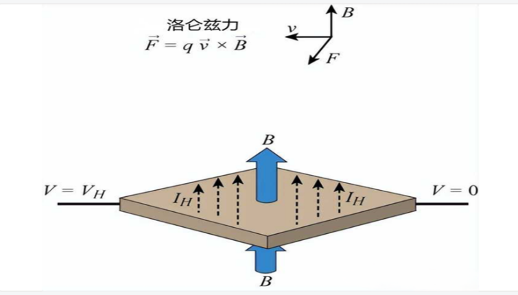
Hall effect and Lorentz force: the blue arrow B represents the magnetic field passing vertically through the conductive plate
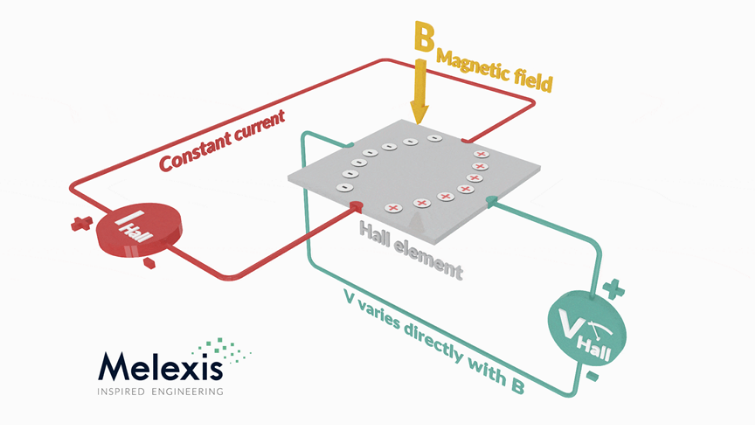
The principle of the Hall effect states that when a current-carrying conductor or semiconductor is introduced into a perpendicular magnetic field, a voltage can be measured at a position perpendicular to the current path.
The Hall voltage, denoted as VH, is given by the formula:
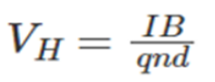
· VH is the Hall voltage on the conductive plate
· I is the current flowing through the sensor
· B is the magnetic field strength
· q is the charge
· n is the number of charge carriers per unit volume
· d is the thickness of the sensor
3. Principle of Hall Effect Sensors
When the magnetic flux density around the sensor exceeds a certain preset threshold, the sensor detects it and generates an output voltage called the Hall voltage (VH). The specific principle is shown in the figure below.
A Hall effect sensor basically consists of a thin rectangular piece of p-type semiconductor material, such as gallium arsenide (GaAs), indium antimonide (InSb), or indium arsenide (InAs), through which a continuous current passes.
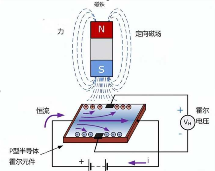
Schematic diagram of the Hall effect sensor
When a Hall effect sensor is placed in a magnetic field, the magnetic flux lines exert a force on the semiconductor material, causing charge carriers (electrons and holes) to deflect to either side of the semiconductor plate. This movement of charge carriers is the result of the magnetic force they experience as they pass through the semiconductor material.
As these electrons and holes move sideways, a potential difference is generated between the two sides of the semiconductor material due to the accumulation of these charge carriers. The movement of electrons through the semiconductor material is then affected by an external magnetic field perpendicular to it, and this effect is more pronounced in flat rectangular materials.
The Hall effect provides information about the type of magnetic pole and the magnitude of the magnetic field. For example, a south pole will cause the device to produce a voltage output, while a north pole will have no effect. Typically, Hall effect sensors and switches are designed to be in an "off" state (open-circuit state) when no magnetic field is present. They only "turn on" (closed-circuit condition) when exposed to a magnetic field of sufficient strength and polarity.
In its simplest form, the sensor operates as an analog sensor, directly returning a voltage. With a known magnetic field, the distance from the Hall plate can be determined. Using a group of sensors, the relative position of the magnet can be inferred.
Usually, Hall effect sensors are combined with circuits that allow the device to operate in digital (on/off) mode, and in this configuration, they may be referred to as switches. The figure below shows a wheel with two magnets passing by a Hall effect sensor.
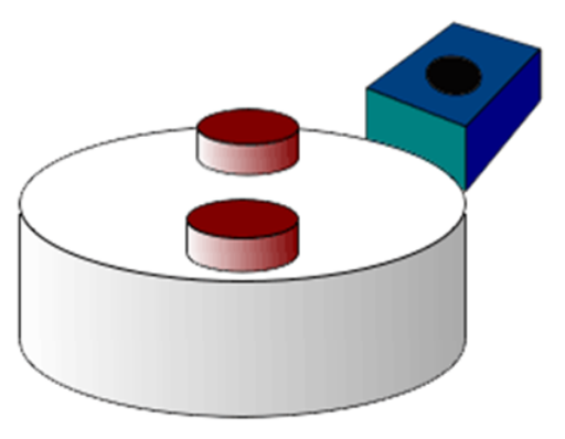
A wheel with two magnets passing by a Hall effect sensor

Site Map | 萨科微 | 金航标 | Slkor | Kinghelm
RU | FR | DE | IT | ES | PT | JA | KO | AR | TR | TH | MS | VI | MG | FA | ZH-TW | HR | BG | SD| GD | SN | SM | PS | LB | KY | KU | HAW | CO | AM | UZ | TG | SU | ST | ML | KK | NY | ZU | YO | TE | TA | SO| PA| NE | MN | MI | LA | LO | KM | KN
| JW | IG | HMN | HA | EO | CEB | BS | BN | UR | HT | KA | EU | AZ | HY | YI |MK | IS | BE | CY | GA | SW | SV | AF | FA | TR | TH | MT | HU | GL | ET | NL | DA | CS | FI | EL | HI | NO | PL | RO | CA | TL | IW | LV | ID | LT | SR | SQ | SL | UK
Copyright ©2015-2025 Shenzhen Slkor Micro Semicon Co., Ltd
