+86 0755-83044319

Technical Blogs

/
/

What are the functions of TVS diodes

release time:2022-11-18Author source:slkor-ganBrowse:921

       
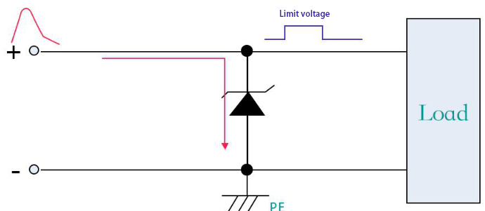
          The TVS tube is a high-efficiency protection device. When the two ends are subjected to an instantaneous high-energy impact, the TVS tube can instantly convert its high-resistance characteristics into low-resistance characteristics, absorb large currents, and clamp the voltage at both ends of the TVS tube. At a certain value (the withstand voltage value of the TVS tube), the rear circuit is protected from the impact of transient high energy and the safety of the circuit is protected. As shown below. To put it simply, if the voltage impact that the circuit can withstand is not higher than DC24V, then weld a 26V TVS tube at the power supply. When the power supply voltage does not exceed 26V, the TVS tube is in a high-impedance state; After a pulse higher than 26V, the TVS tube can quickly clamp the circuit voltage to 24V, thus ensuring the safety of the circuit board.

10.jpg

The role of TVS diodes

In general, the functions of TVS diodes are:
(1) Adding TVS diodes to signal and power lines can prevent microprocessors or single-chip microcomputers from malfunctioning due to instantaneous fat surges, such as electrostatic discharge effects, AC power surges, and switching power supply noise.
(2) The electrostatic discharge effect can release pulses of more than 10000V and 60A, and can last for 10ms; while general TTL devices, when encountering 10V pulses of more than 30ms, will lead to damage. The use of TVS diodes can effectively absorb pulses that would damage devices and eliminate interference (Crosstalk) caused by switching between buses.
(3) Placing the TVS diode between the signal line and the ground can prevent the data and control bus from being affected by unnecessary noise.


How TVS Diodes Work
         The transient voltage suppressor (TransientVoltageSuppressor) is referred to as TVS tube. The electrical characteristics of TVS tube are determined by the P-N junction area, doping concentration and wafer resistance. Its ability to withstand surge current is proportional to its P-N junction area. TVS is widely used in the protection of semiconductors and sensitive devices, usually for the protection of secondary power supply and signal circuits, and anti-static. It is characterized by fast response (ps level), small size, high pulse power, and low clamping voltage. Its 10/1000μs wave pulse power ranges from 400W to 30KW, and the pulse peak current ranges from 0.52A to 544A; the breakdown voltage has a series of values from 6.8V to 550V, which is convenient for use in circuits with various voltages.
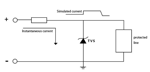
The device is connected in parallel in the circuit. When the circuit is working normally, it is in the cut-off state (high resistance state), which does not affect the normal operation of the circuit. When the circuit has an abnormal overvoltage and reaches its breakdown voltage, it quickly changes from a high resistance state to a high resistance state. The low-impedance state provides a low-impedance conduction path for the instantaneous current, and at the same time clamps the abnormal high voltage within a safe level, thereby protecting the protected IC or circuit; when the abnormal overvoltage disappears, it returns to the high-impedance state, and the circuit works normally.

20.jpg


TVS Diode Characteristics

30.jpg

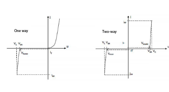
TVS Diode Characteristic Curve

Main characteristic parameters
      ①Reverse off-state voltage (cut-off voltage) VRWM and reverse leakage current IR: Reverse off-state voltage (cut-off voltage) VRWM indicates the highest voltage at which the TVS tube does not conduct, and there is only a small reverse leakage current under this voltage IR.
      ②Breakdown voltage VBR: The voltage when the TVS tube passes the specified test current IT, which is the sign voltage indicating that the TVS tube is turned on (the numbers in the P4SMA, P6SMB, 1.5SMC, P4KE, P6KE, and 1.5KE series models are breakdown The nominal value of the voltage, other series of figures are the reverse off-state voltage value).
The breakdown voltage of the TVS tube has an error range of ±5% (the one without "A" is ±10%).
       ③Pulse peak current IPP: The maximum peak current of the 10/1000μs wave that the TVS tube allows to pass (the peak current of the 8/20μs wave is about 5 times that), exceeding this current value may cause permanent damage. In the same series, the higher the breakdown voltage of the tube, the smaller the peak current allowed to pass.
       ④Maximum clamping voltage VC: The voltage presented at both ends of the TVS tube when the pulse peak current IPP flows.
       ⑤Pulse peak power Pm: The pulse peak power Pm refers to the product of the pulse peak current IPP of 10/1000μs wave and the maximum clamping voltage VC, that is, Pm=IPP*VC.


TVS Diode Applications
      ①Selection of pulse peak current IPP and maximum clamping voltage VC: When TVS tube is used alone, the appropriate model of IPP should be selected according to the maximum surge current that may appear on the line. When the TVS tube is used as the second level of protection, generally 500W ~ 600W is enough. It should be noted that the maximum clamping voltage VC at this time should not be greater than the maximum surge voltage (safety voltage) that the protected equipment can withstand.
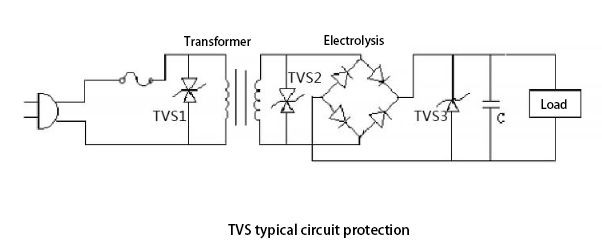
       ② When used for signal transmission circuit protection, attention must be paid to the frequency or transmission rate of the transmitted signal. When the signal frequency (transmission rate) ≥ 10MHz (Mb/s), Cj should be ≤ 60pF; when the signal frequency (transmission rate) ≥ 100MHz (Mb/s), Cj should be ≤ 20pF. When the signal frequency or transmission rate is high, low capacitance series tubes should be selected. When the low-capacitance series still cannot meet the requirements, the TVS tube should be connected to the bridge composed of fast recovery diodes to reduce the total equivalent capacitance and increase the transmission signal frequency. For the circuit shown in the figure below, the maximum transmission frequency can reach above 20MHz.

40.jpg

       TVS1 protects the entire circuit including the transformer.
       TVS2 provides a high degree of protection for the subsequent circuit (the entire circuit except the transformer). Due to the physical nature of the transformer as a large series resistance, there is little chance of breaking the circuit when it is hit by a surge.
       TVS3 provides comprehensive protection for the load. Here, lower cost unipolar TVS diodes are used. If only TVS3 is used in the circuit, since the bridge is not protected by TVS, the bridge should use a device with a higher voltage and current ratio to prevent damage.


Service hotline

+86 0755-83044319

Hall Effect Sensor

Get product information

WeChat

WeChat