Service hotline
+86 0755-83044319

release time:2025-07-22Author source:SlkorBrowse:1249
An Operational Amplifier (abbreviated as op-amp) is a direct-coupled, differential mode input, typically single-ended output high-gain voltage amplifier. It can generate an output potential (relative to ground) that is hundreds of thousands of times larger than the potential difference at the input. It got its name because it was initially mainly used in analog computing circuits such as addition and subtraction operations.
Working Principle of Operational Amplifier
The differential input of an operational amplifier includes a non-inverting input voltage and an inverting input voltage. An ideal operational amplifier only amplifies the difference between the two voltages, which is called the differential mode input voltage. The output voltage of the operational amplifier is given by the following formula:
Vout = (V+ - V-) * Ado
where Ado is the open-loop differential gain of the operational amplifier.

Ideal Operational Amplifier
An ideal operational amplifier usually has the following characteristics:
1. Infinite open-loop gain (Ado = +∞): An important property of an ideal operational amplifier is that in the open-loop state, the differential signal at the input has an infinitely large voltage gain, which makes the operational amplifier very suitable for adding a negative feedback configuration in practical applications.
2. Infinite input impedance (Zin/Rin = ∞): The input terminals of an ideal operational amplifier do not allow any current to flow in, that is, the current signals at the V+ and V- terminals are always zero, which means the input impedance is infinite.
3. Zero input offset voltage
4. Infinite bandwidth (BW = ∞) with zero phase shift and infinite slew rate: An ideal operational amplifier will amplify input signals of any frequency with the same differential gain, without changing due to the change of signal frequency.
5. Zero output impedance (Zout/Rout = 0): The output terminal of an ideal operational amplifier is a perfect voltage source. No matter how the current flowing to the amplifier load changes, the output voltage of the amplifier remains constant, that is, the output impedance is zero.
6. Zero noise
7. Infinite common-mode rejection ratio (CMRR = ∞): An ideal operational amplifier can only respond to the voltage difference between the V+ and V- terminals, that is, it only amplifies the (V+ - V-) part. The common part of the two input signals (i.e., the common-mode signal) is completely ignored.
8. Infinite power supply rejection ratio
All these idealizations cannot be fully realized. Equivalent resistors and capacitors can be used in the operational amplifier model to simulate the non-infinite or non-zero parameters of a real operational amplifier. In this way, designers can take these influences into account in the overall performance of the final circuit. The impact of some parameters on the final design may be negligible, but other parameters that actually restrict the final performance must be calculated.
Common Application Designs
(1) Inverting Closed-Loop Amplifier

The above figure shows a circuit of an inverting closed-loop amplifier. Assuming this closed-loop amplifier uses an ideal operational amplifier, due to its infinite open-loop gain, the two input terminals of the operational amplifier are virtual ground. Also, because the input impedance is infinite, the current from Vin to V- is equal to the current from V- to Vout, so:

(2) Non-Inverting Closed-Loop Amplifier

The above figure shows a circuit of a non-inverting closed-loop amplifier. The negative feedback determines the closed-loop gain Acl=Vout/Vin through the voltage-divider resistors Rf and Rg. Balance is established when Vout is just sufficient to make the voltage at the inverting terminal equal to Vin. Therefore, the voltage gain of the entire circuit is 1 + Rf/Rg. The output voltage formula is:

(3) Adder

The above figure shows an adder circuit. Under the condition of an ideal operational amplifier, because the input impedance is infinite, the current through R1 is equal to the current through R2, and similarly, the current through R3 is equal to the current through R4. So:
(V1-V+)/R1=(V+-V2)/R2
(Vout-V-)/R3=V_/R4
Also because of virtual short circuit, there is:V+=V_
Then it can be deduced that :Vout=V1+V2
(4) Integrator Circuit

The above figure shows an integrator circuit. Under the condition of an ideal operational amplifier, the open-loop gain is infinite, the voltage at the inverting input terminal is equal to that at the non-inverting terminal, and because the input impedance is infinite, the current through R1 is equal to the current through C1.
The current passing through R1 i=V₁/R₁
The current passing through C1 i=C·dU./dt
So Vout =((-1/(R₁·C₁)·fV₁dt
The output voltage is proportional to the integral of the input voltage over time, which is why it is called an integrator circuit.
(5) Differentiator Circuit

The above figure shows a differentiator circuit. Under the condition of an ideal operational amplifier, the open-loop gain is infinite, the voltage at the inverting input terminal is equal to that at the non-inverting terminal, and because the input impedance is infinite, the current through R1 is equal to the current through C1.

If V1 is a suddenly applied DC voltage, the output Vout corresponds to a pulse in the opposite direction to V1.

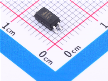
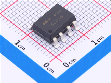
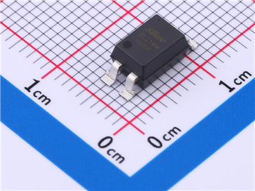
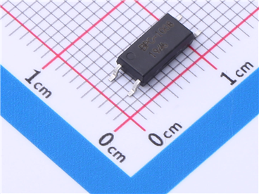
Slkor SL8634XS14 General Op-amp SOP-14
About SLKOR:
SLKOR, headquartered in Shenzhen, China, is a rapidly emerging national high-tech enterprise in the power semiconductor sector. With R&D centers in Beijing and Suzhou, its core technical team originates from Tsinghua University. As an innovator in silicon carbide (SiC) power device technology, SLKOR's products are widely used in new energy vehicles, photovoltaic power generation, industrial IoT, and consumer electronics, providing critical semiconductor solutions to over 10,000 clients globally.
The company delivers more than 2 billion units annually, with its SiC MOSFETs and 5th-generation ultrafast recovery SBD diodes setting industry benchmarks in efficiency ratio and thermal stability. SLKOR holds over 100 invention patents and offers 2,000+ product models, continually expanding its IP portfolio across power devices, sensors, and power management ICs. Certifications including ISO 9001, EU RoHS/REACH, and CP65 compliance demonstrate the company's steadfast commitment to technological innovation, lean manufacturing, and sustainable development.

Site Map | 萨科微 | 金航标 | Slkor | Kinghelm
RU | FR | DE | IT | ES | PT | JA | KO | AR | TR | TH | MS | VI | MG | FA | ZH-TW | HR | BG | SD| GD | SN | SM | PS | LB | KY | KU | HAW | CO | AM | UZ | TG | SU | ST | ML | KK | NY | ZU | YO | TE | TA | SO| PA| NE | MN | MI | LA | LO | KM | KN
| JW | IG | HMN | HA | EO | CEB | BS | BN | UR | HT | KA | EU | AZ | HY | YI |MK | IS | BE | CY | GA | SW | SV | AF | FA | TR | TH | MT | HU | GL | ET | NL | DA | CS | FI | EL | HI | NO | PL | RO | CA | TL | IW | LV | ID | LT | SR | SQ | SL | UK
Copyright ©2015-2025 Shenzhen Slkor Micro Semicon Co., Ltd
