Service hotline
+86 0755-83044319

release time:2025-07-21Author source:SlkorBrowse:1070
Thyristor conduction conditions: First, a forward voltage must be applied between the anode and cathode of the thyristor; second, a forward voltage must also be applied to the gate. Both conditions must be met simultaneously for the thyristor to enter the conduction state.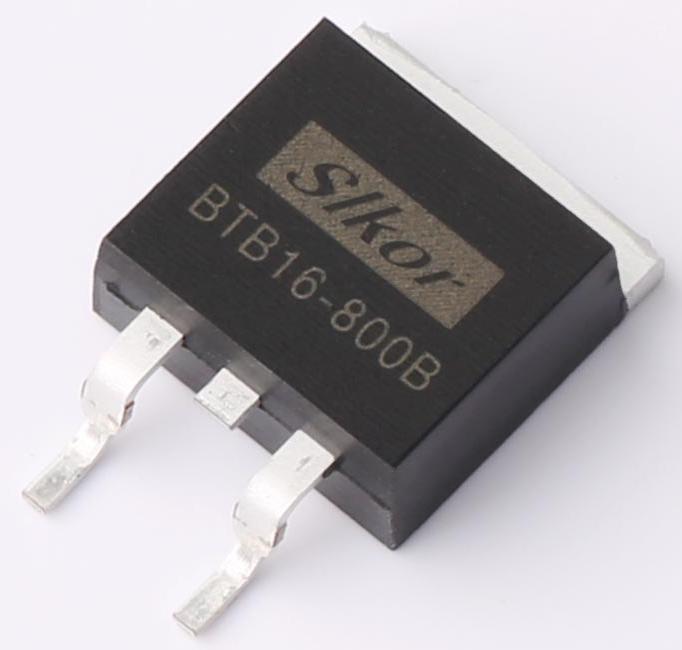
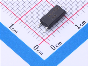
Slkor BTB16-800B Unidirectional Silicon Control Rectifier SCR TO-263
To put it simply, for a thyristor to conduct:
(1) A signal must be applied;
(2) The anode must be at a higher potential than the cathode (i.e., a forward voltage must exist between them).
Once a thyristor is conducting, it remains conducting even if the gate voltage is reduced or removed. In simple terms, it stays on even when the signal is gone.
Thyristor turn-off conditions: Reduce or remove the forward voltage between the anode and cathode, so that the anode current drops below the minimum holding current.
To simplify:
● For a thyristor to turn on, it needs both a signal and the anode to be at a higher potential than the cathode.
● Once turned on, it stays on even if the signal is removed (a single signal is enough to trigger it).
● To turn it off, either cut off the power supply to the anode-cathode circuit or make the anode potential lower than the cathode potential.
● A unidirectional thyristor is like a controllable diode, with its conduction controlled by a signal. Thus, it allows direct current to pass through unimpeded; for alternating current, it conducts during the positive half-cycle but not the negative half-cycle (the diode here acts as a rectifier).
A bidirectional thyristor (triac) can conduct alternating current.
Case Analysis of Thyristor Control Circuits
Unidirectional Thyristors (Components that can control diodes)
Light-Controlled Electronic Switch
● A light-controlled electronic switch uses the conduction and blocking of a thyristor to "turn on" and "turn off". The conduction and blocking of the thyristor are controlled by the intensity of natural light (or artificial light).
● This device is suitable for streetlights, dormitory corridor lights, or lighting in other public places, automatically turning off during the day and on at night to save electricity.
Working principle:
As shown in the circuit diagram above:
1. 220V AC is converted into pulsating DC voltage through bulb H and full-bridge rectification, serving as a forward bias (approximately 300V pulsating DC). When this current flows through the diode of the VS unidirectional thyristor to the other end, the bulb lights up. For this to happen, the gate of the thyristor must receive a signal voltage, which requires the 9014 transistor to conduct.
2. How does the 9014 conduct?
The 300V pulsating DC is divided by R1 (100kΩ), R2 (470kΩ), and D (photoresistor). Meanwhile, R1 and DW (zener diode) form a voltage divider, and DW clamps the voltage across R2 and the photoresistor at 6.8V, preparing for the transistor to conduct.
● During the day, when brightness exceeds a certain level, the photoresistor D exhibits a low resistance (≤1kΩ). The entire 6.8V voltage drops across the transistor's base, causing transistor V to cut off (NPN transistors cut off at high levels). No current flows from its emitter, so the unidirectional thyristor VS remains blocked due to the lack of a trigger current, and bulb H does not light. Resistor R1 and zener diode DW limit the transistor's bias voltage to no more than 6.8V, protecting the transistor.
● At night, when brightness falls below a certain level, the photoresistor D exhibits a high resistance (≥100kΩ). This causes transistor V to conduct forward (NPN transistors conduct at low levels), with approximately 0.8V at the emitter, triggering the thyristor VS to conduct and lighting bulb H.
● Installation and Debugging: During installation, place the soldered printed circuit board in a transparent plastic case and secure it. Connect it in series with the controlled light H, and position it to face the sky or a bright area near a building's light-receiving window, avoiding direct exposure to nighttime lights within 3 meters.
● Debugging should be done at dusk. Adjust the resistance of RP so that the controlled light H turns on at an appropriate brightness level.
Simple Delay Lighting
● Circuit principle: The circuit of this delay light is as shown in the attached diagram, with the delay circuit enclosed in the dashed box. In the diagram, K is a switch.
● When K is closed, current flows directly through K to light the bulb, and other circuits remain inactive.
● When K is turned off, the 220V voltage is rectified by the diode. On one hand, it charges capacitor C through R1; during the charging process of C, no current flows through R2, so transistor V remains cut off. On the other hand, this voltage provides a trigger voltage to the thyristor SCR through R3 and R4, keeping the thyristor conducting. Thus, the light stays on for a period after being turned off.
● Once capacitor C is fully charged, current flows through R1 and R2 to the base of transistor V, turning transistor V from cut-off to conduction. When the transistor conducts, current flows through the bulb to R3 and then through the transistor to the negative pole. At this point, because the transistor has low impedance, no current flows through R4 to the thyristor's gate, so the thyristor SCR turns off. Since current flows through the bulb and R3 (220kΩ) has a high resistance, the voltage across the bulb is very low, and the light goes out.
● During the delay period after the light is turned off in this circuit, the delay time is determined by the values of resistor R1 and capacitor C.
● This circuit uses a unidirectional thyristor. During the delay period after the light is turned off, the brightness of the lamp is approximately half of its brightness when it is fully on, which meets people's visual needs while saving energy.
● Circuit production: For the unidirectional thyristor SCR in this circuit, use MCR100-8 with a voltage rating of at least 600V. The bulb power should not exceed 100W. The diode VD is 1N4007, and the transistor V is C1815. All resistors are 1/8W carbon film resistors.
2. Bidirectional Thyristors (Components that can control AC)
The following is a classic bidirectional thyristor circuit, which uses optocoupler isolation to control high-voltage circuits with low-voltage signals, enabling continuous dimming of lights.

Site Map | 萨科微 | 金航标 | Slkor | Kinghelm
RU | FR | DE | IT | ES | PT | JA | KO | AR | TR | TH | MS | VI | MG | FA | ZH-TW | HR | BG | SD| GD | SN | SM | PS | LB | KY | KU | HAW | CO | AM | UZ | TG | SU | ST | ML | KK | NY | ZU | YO | TE | TA | SO| PA| NE | MN | MI | LA | LO | KM | KN
| JW | IG | HMN | HA | EO | CEB | BS | BN | UR | HT | KA | EU | AZ | HY | YI |MK | IS | BE | CY | GA | SW | SV | AF | FA | TR | TH | MT | HU | GL | ET | NL | DA | CS | FI | EL | HI | NO | PL | RO | CA | TL | IW | LV | ID | LT | SR | SQ | SL | UK
Copyright ©2015-2025 Shenzhen Slkor Micro Semicon Co., Ltd
