


Service Hotline
Tech Applications

Tech Applications
Slkor SL3404 N‑Channel MOSFET: 30V Withstand‑voltage, 5A, SOT‑23 Power Switch MOSFET
2026-11-19
260
SL3404 is an N-channel power MOSFET from Slkor in SOT-23 surface-mount package. It has 30V drain-source withstand-voltage and 5A continuous drain current, with an integrated body diode. This device delivers low on-state resistance and fast switching response, and is compatible with surface-mount technology. It targets low-voltage medium-and-low-current switching control applications. All electrical parameters follow the device datasheet with a reference ambient temperature of 25℃.
About Slkor:
SL3404To Product Page
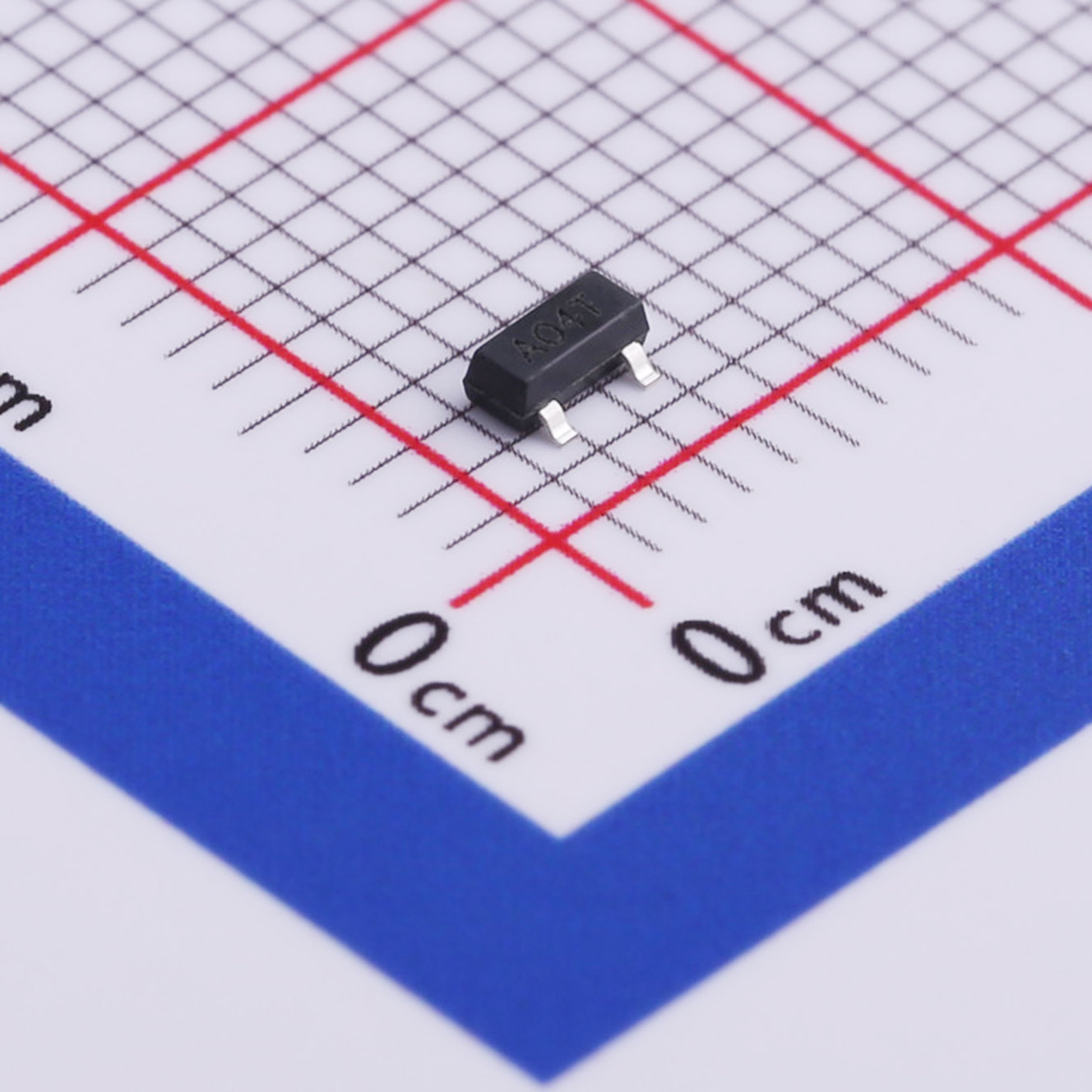
Slkor Power Switching MOSFET SL3404 Product Image
1. Core Product Parameters
Unless otherwise noted, electrical characteristics are tested at ambient temperature of 25℃, with pulse width no more than 300μs and duty cycle no more than 2.0%.
1.1 Absolute Maximum Ratings
- Drain-source voltage: 30V
- Gate-source voltage: 20V
- Continuous drain current: 5A
- Pulsed drain current: 18A
- Total device dissipation at ambient temperature of 25℃: 1400mW
- Maximum junction temperature: 150℃
- Storage temperature range: -55℃ to +150℃
1.2 Electrical Characteristics
- Drain-source breakdown voltage, test condition: drain current 250uA, gate-source voltage 0V, minimum value 30V
- Gate threshold voltage, test condition: drain current 250uA, range from 1V to 3V
- Body diode forward voltage drop, test condition: source current 1A, gate-source voltage 0V, typical value 0.7V, maximum value 1V
- Zero gate-voltage drain current, test condition: gate-source voltage 0V, drain-source voltage 30V, maximum value 1uA
- Gate-body leakage current, test condition: gate-source voltage 20V, drain-source voltage 0V, maximum value 100nA
- Drain-source on-state resistance, test condition: drain current 5A, gate-source voltage 10V, typical value 25mΩ, maximum value 28mΩ
- Drain-source on-state resistance, test condition: drain current 3A, gate-source voltage 4.5V, typical value 40mΩ, maximum value 45mΩ
- Input capacitance, test condition: gate-source voltage 0V, drain-source voltage 15V, test frequency 1MHz, typical value 545pF
- Output capacitance, test condition: gate-source voltage 0V, drain-source voltage 15V, test frequency 1MHz, typical value 66pF
- Turn-on time, test condition: drain-source voltage 15V, gate-source voltage 10V, generator resistance 6Ω, typical value 9.6ns
- Turn-off time, test condition: drain-source voltage 15V, gate-source voltage 10V, generator resistance 6Ω, typical value 39ns
1.3 Package Dimension Parameters
Package form: SOT-23. All dimensions are in millimeters. Body height ranges from 0.900 to 1.150, body length ranges from 2.800 to 3.000, body width ranges from 1.200 to 1.400. Allowable lead bending angle is 0°-8°, typical lead pitch is 0.950. It is a standard three-pin surface-mount package.
2. Key Product Features
- Compact SOT-23 surface-mount package supports SMT assembly and saves PCB layout space.
- Drain-source withstand-voltage reaches 30V, supports 5A continuous operating current and maximum 18A short-time pulsed current.
- Low on-state resistance, ensuring low conduction loss under 10V and 4.5V gate driving conditions.
- Integrated on-chip body diode to realize freewheeling function for inductive loads.
- Good switching performance with typical turn-on time of 9.6ns and typical turn-off time of 39ns, meeting general switching requirements.
- Gate threshold voltage ranges from 1V to 3V. It supports 4.5V low-voltage driving and matches output level of most logic and power ICs.
- Wide temperature adaptability. Maximum junction temperature is 150℃ and storage temperature ranges from -55℃ to +150℃.
3. Main Application Fields
- Load switches inside various consumer electronics for power path on-off control.
- Protection, charge and discharge control for lithium-ion and polymer battery loops.
- Power switching units for DC-DC conversion circuits and small-size LDO circuits.
- Drive and control loops for LED lighting.
- Power control circuits inside portable devices and small household appliances.
- Power and signal switching for low-voltage auxiliary loops of industrial equipment.
4. Engineering Design Recommendations
- The heat dissipation capacity of SOT-23 package is limited. Power derating shall be adopted in practical design. Long-term operation at maximum power dissipation is not recommended. Evaluate heat dissipation capacity of PCB copper foil under high-current conditions.
- Gate-source voltage shall not exceed the rated upper limit of 20V. Excessive voltage will cause irreversible damage to the device gate.
- For high-frequency switching design, take driving loss caused by input capacitance and output capacitance into account. Select appropriate gate driving resistance to suppress circuit oscillation.
- For inductive-load applications using the built-in body diode for freewheeling, pay attention to diode current and heating. Add external freewheeling components when necessary.
- Pulsed drain current applies only to short-time surge conditions and cannot be used as continuous operating current. Reserve sufficient safety margin for voltage and current during design.
- Keep gate traces as short as possible to reduce parasitic line inductance and voltage spikes generated during switching.
- Device operating junction temperature shall not exceed 150℃. Further reduce actual operating current under high ambient temperature.
5. Product Summary
SL3404 is an N-channel power MOSFET in SOT-23 package, featuring 30V withstand-voltage and 5A continuous current rating. It has low on-state resistance, favorable switching response and integrated body diode, and is suitable for mass surface-mount production. This device is intended for low-voltage medium-and-low-current switching applications such as consumer electronics, battery management and compact power supplies. Restricted by package thermal performance, it is not fit for long-time high-power operation. Hardware designers should complete derating assessment for voltage, current and power consumption, optimize gate driving and PCB layout. The device must operate within absolute maximum ratings specified in the datasheet to guarantee stable circuit performance.
About Slkor:
SLKOR's product portfolio includes discrete semiconductor devices such as diodes, transistors, and power devices, as well as integrated circuits such as linear regulators, DC-DC converters, interface chips, Hall sensors, ADCs, and battery management systems (BMS)
SL3404To Product Page
Related Recommendations




 粤公网安备44030002007346号