


Service Hotline
Tech Applications

Tech Applications
Slkor SL2301S P‑Channel Power MOSFET: 20V withstand voltage, 2.4A, SOT‑23 Power Switch Field‑Effect Transistor
2026-11-10
84
SL2301S is a P-channel power MOSFET in SOT-23 package developed by Slkor. It features 20 V drain-source withstand voltage and 2.4 A continuous drain current with low on-state resistance. This lead-free surface-mount device is suitable for power management, load switch, PWM control and other circuit scenarios. This document sorts out its parameters, features, applications and relevant suggestions for engineering usage.
About Slkor:
SL2301STo Product Page
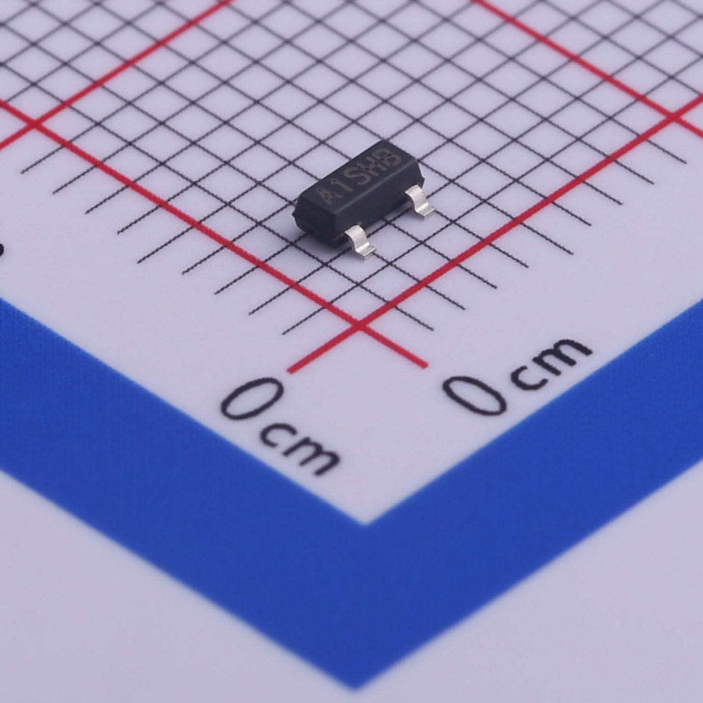
Slkor Power Switch MOSFET SL2301S Product Image
1. Core Product Parameters
1.1 Maximum Ratings (TA = 25 ℃)
- Drain-source breakdown voltage: -20 V
- Gate-source voltage: +8 V
- Continuous drain current: -2.4 A
- Pulsed drain current: -10 A
- Total device power dissipation: 900 mW
- Maximum junction temperature: 150 ℃
- Storage temperature range: -55 ℃ ~ +150 ℃
1.2 Electrical Characteristics (TA = 25 ℃, Pulse Width ≤300 μs; Duty Cycle ≤2.0%)
- Drain-source breakdown voltage: -20 V
- Gate threshold voltage range: -0.4 V ~ -1.5 V
- Maximum body diode forward voltage drop: -1.5 V
- Zero-gate-voltage drain current: -10 μA ~ -1 μA (Test at TA=55 ℃)
- Maximum gate body leakage current: +100 nA
- Maximum on-state resistance at VGS=-4.5 V: 140 mΩ
- Maximum on-state resistance at VGS=-2.5 V: 200 mΩ
- Typical input capacitance: 600 pF
- Typical output capacitance: 120 pF
- Typical turn-on time: 8 ns
- Typical turn-off time: 60 ns
1.3 Package
Package type: SOT-23 surface-mount package.
2. Core Product Features
- High power and current-handling capability;
- Lead-free construction;
- SOT-23 surface-mount package saves PCB space and supports automated reflow soldering;
- Low on-state resistance under different gate-drive voltages to reduce conduction loss;
- Switching speed meets requirements for general-purpose switching circuits.
3. Main Application Fields
- PWM related circuits;
- Load switch circuits;
- Various power management circuits.
4. Suggestions for Engineering Design
- Operating conditions shall never exceed absolute maximum ratings including voltage, current, power dissipation and junction temperature. Thermal design is required for long-term operation to keep junction temperature below 150 ℃. Storage temperature shall be kept between -55 ℃ and +150 ℃.
- Gate-source voltage shall not exceed +8 V. Exceeding this rating will damage the gate oxide layer and cause device failure.
- The integrated body diode can be used for freewheeling in reverse loops. Pay attention to power loss caused by its forward voltage drop.
- Switching parameters are measured under narrow-pulse and low-duty-cycle conditions. Additional switching loss introduced by device capacitances shall be evaluated for continuous high-frequency operation according to actual working frequency.
- Pulsed drain current is only valid for short-pulse conditions and cannot be used as continuous operating current.
- Keep gate traces short in PCB layout to reduce parasitic inductance and suppress oscillation. Due to limited thermal area of SOT-23 package, increase copper pour area for better heat dissipation under high-current conditions.
5. Product Summary
SL2301S is a P-channel power MOSFET in SOT-23 package with 20 V withstand voltage and 2.4 A continuous current. It has good on-resistance performance and adopts lead-free surface-mount housing. It targets medium-and-low-power load switches, PWM and power-management circuits for consumer-electronic power systems. To ensure long-term stable performance, designers must respect absolute maximum ratings and optimize thermal performance as well as PCB layout.
About Slkor:
SLKOR's product portfolio includes discrete semiconductor devices such as diodes, transistors, and power devices, as well as integrated circuits such as linear regulators, DC-DC converters, interface chips, Hall sensors, ADCs, and battery management systems (BMS)
SL2301STo Product Page
Related Recommendations




 粤公网安备44030002007346号